Failure Analysis And Preventive Measures Of Sanitary Diaphragm Valves
Sanitary Diaphragm Valve Fault analysis and preventive measures
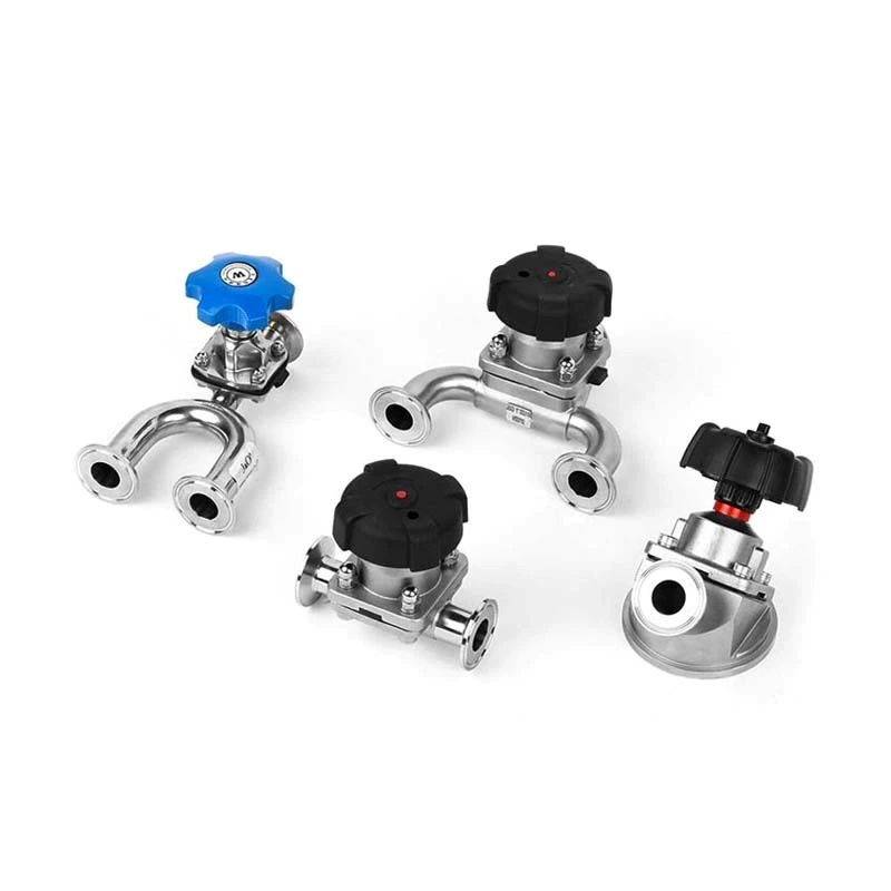
The main components of the diaphragm valve are the valve head (upper valve cover, lower valve cover, spring tray, spring), valve stem, adjusting nut and valve body. The rated working pressure of the diaphragm is 0.69~0.75 MPa. After the oil pressure is established on the upper part of the diaphragm, the diaphragm moves downward, and while overcoming the spring elastic force, the valve stem moves downward to close the valve; when the upper part of the diaphragm loses pressure, the spring rebounds and drives the valve stem upward, and the valve opens quickly.
The steam turbine adopts a digital electro-hydraulic control system, in which the hydraulic diaphragm valve (hereinafter referred to as the diaphragm valve) is a key component connecting the control oil safety oil circuit and the lubricating oil emergency shut-off oil circuit. When the manual brake is opened or the main engine is overspeeding, and the lubricating oil system emergency shut-off oil leaks, the oil pressure on the upper part of the diaphragm valve is released, and the valve stem moves upward quickly, so that the control system safety oil is connected to the return oil and the pressure is released, and the automatic main steam valve and regulating steam valve are quickly closed, and the unit is shut down.
2 Fault phenomenon
(1) Leakage on the valve cover sealing surface. The diaphragm valve head is composed of an upper and lower valve cover and a diaphragm fastened with bolts. The chamber between the upper valve cover and the diaphragm introduces the emergency shut-off oil of the main engine lubricating oil system. This sealing surface has been leaking since the unit was put into operation, and the effect of multiple treatments has not been good.
(2) The diaphragm ruptures, causing the oil pressure to disappear and the diaphragm valve to open. The diaphragm of the diaphragm valve ruptures, and the lubricating oil flows to the high-temperature pipeline. The diaphragm has to be shut down and replaced with a new diaphragm. After inspection, it was found that there was a 3 mm diameter perforation at the contact point between the diaphragm and the spring tray.
3 Cause Analysis
(1) The adjustment valve (for pressure relief) for adjusting the oil pressure is a needle valve. Due to the influence of factors such as vibration, it will gradually close during operation, causing the oil pressure to rise slowly. If the adjustment is not timely, the diaphragm will operate under an overpressure of 0.80-0.85 MPa, which accelerates the damage of the diaphragm. In addition, when the main engine was doing an overspeed test, the speed increased to about 3,300 r/min. Due to untimely adjustment, the oil pressure of the diaphragm valve once increased to 0.9 MPa, causing short-term overpressure.
(2) The design width of the upper and lower valve cover sealing surfaces is too small. Inspection found that the effective sealing width (extrusion deformation part) of the leaking diaphragm is less than 5 mm as a whole, and the narrowest part is only 2 mm.
(3) The thickness of the upper and lower valve cover plates is only 5 mm. According to the effective diameter of the upper valve cover of 240 mm and the oil pressure of 0.8 MPa, the pressure is about 36,170 N. The valve cover plate is deformed by force, and the sealing plane of the upper and lower valve covers has an inward opening, which further narrows the sealing surface and aggravates the leakage.
(4) The diaphragm installation process is unreasonable. The maintenance personnel are not familiar with the structural principle of the diaphragm valve. When installing the new diaphragm, they did not take measures to loosen the adjustment nut to make the spring lose its force, but carried out it with the diaphragm valve open. Because the spring tray is in a high position, the diaphragm contacts the upper valve cover, but there is a 20 mm gap with the lower valve cover. In order to fasten the three together, they must be forcibly connected with long-rod bolts (the purpose is to overcome the elastic force of the spring). At this time, the bolt hole of the diaphragm is pulled and deformed, which is easy to cause damage, and the position of its bolt hole is offset inward relative to the bolt hole of the valve cover and becomes elliptical, the sealing surface becomes narrower, and the sealing effect becomes worse.
(5) There are bubbles in the gel part of the diaphragm, and there is a stratification phenomenon inside. The maintenance personnel did not check carefully before replacement and failed to discover it in time, leaving hidden faults after installation.
(6) Accidental damage to the diaphragm. The diaphragm is not properly protected during storage and installation. The diaphragm contacts corrosive liquids or collides and squeezes with the sharp parts of tools and parts (such as raised corners of the spring tray), which damages and scratches the diaphragm surface. Failure to handle it in time causes leakage hazards.
4 Preventive measures
(1) Carefully inspect the goods and avoid using unqualified products. The diaphragm should be properly stored and stored; during the installation process, care should be taken not to allow the diaphragm to be hit or scratched; pay attention to check the upper valve cover and spring tray, remove burrs, and keep the contact parts smooth. After the above treatment, the diaphragm valve operates well, ensuring the long-term safe operation of the main equipment.
(2) Prevent the diaphragm from operating at overpressure. The operating personnel should strengthen monitoring and immediately notify the maintenance personnel to calibrate the pressure gauge if the oil pressure exceeds the standard. After confirming that the oil pressure has increased, the adjustment door should be slowly turned to stabilize the pressure within the rated range. In particular, during the unit speed increase and main engine overspeed test, a special person should be assigned to monitor the oil pressure on site and adjust it in time.
(3) Modify the upper and lower valve covers. After demonstration and experiment, while keeping the control oil system safety oil pressure unchanged and not affecting the characteristics of the diaphragm valve, the valve cover is newly processed in the form of the original part, the thickness is increased to 10 mm, and the sealing surface width is expanded inward to 10 mm. This measure was implemented on units 1 and 2 in 2003 and 2004 respectively, with good results and no leakage has occurred so far.
(4) Improve the diaphragm installation process. Before replacing the diaphragm, first measure and record the exposed size of the adjusting nut, and screw it downward so that the spring is free and the spring tray is at the lowest position. At this time, when installing the diaphragm, there is no gap and the bolts can be tightened symmetrically and evenly. After installation, screw the adjusting nut upward to its original position.